summary
The PWM voltage waves generated in the output side of inverter based motor speed controller are transient, causing a variety of problems, such as dielectric breakdown of cable, transformer, or motor. The LC sine-wave filter (LCF) is excellent at converting PWM waves to sine waves and securing stability of device.
- Problems of harmonic
-
-
- High ripple voltage
- Motor operation and lifespan shortening
- Cable damage
- Transformer damage if step-up transformer is installed
- Productivity reduction
-
- Voltage induced inverter lifespan reduction and internal failure
- Malfunction of precision control device
- Instantaneous overvoltage caused by voltage wave distortion
- Distribution line overheating
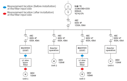
- Application
-
- ① Application loads: motor and device using inverter (inverter output side and inter-load)
- ② Application systems : 220V, 380V, 440V, 3~1000HP
- ③ Application places: factory, ironworks, power plant, sewage treatment plant, dam, incineration plant, intake facility
Product Features
-
- Improvement in voltage and current waveform
-
LCF converts the distorted PWM waveform to sine waves so as to prevent overvoltage of motor terminal and dv/dt.
Usually, a motor increases its capability in the condition of sine wave use. It is designed to prevent dielectric breakdown of motor and expand lifespan of motor.
- Reduction in motor peak voltage
-
A motor running with PWM inverter can increase its terminal peak voltage to the value almost two times higher than DC bus voltage.
It means that the terminal peak voltage of motor increases up to 1700V.
LCF prevents an insulator from being broken down by voltage transient so as to protect a motor and a cable.
- Reduction in ripple and surge of the inverter output side
-
A long-distance cable based motor running with PWM inverter can face its enhanced voltage amplification.
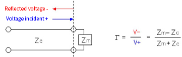
In the case, a relevant factor is determined by motor surge impedance, cable surge impedance, and cable length.
The voltage reflection coefficient R is referred to as the value calculated in the way of converting the reflection value generated by an impedance difference in a connection terminal to the ratio of input voltage to reflection voltage. In short, it is a figure representing a reflection value for input.
CRITICAL CABLE LENGTH
| HP |
R |
Zm |
Zc |
| 25HP |
0.9 |
1500 ohms |
80 ohms |
| 50HP |
0.83 |
750 ohms |
70 ohms |
| 100HP |
0.76 |
375 ohms |
50 ohms |
| 200HP |
0.65 |
188 ohms |
40 ohms |
| 400HP |
0.52 |
94 ohms |
30 ohms |
[Table 1. Typical reflection coefficient and surge impedance]
Zm: motor surge impedance, Zc: cable surge impedance
Motor terminal peak voltage = (1 + R) × DC bus voltage
LCF reduces a reflection coefficient with the total surge impedance and the reactor surge impedance of LCF.
- CRITICAL CABLE LENGTH expansion
-
The available distance of voltage amplification is called critical cable length which is determined with a voltage rise time and an electromagnetic pulse move speed .
CRITICAL CABLE LENGTH = (100 M/Μ SEC X VOLTAGE RISE TIME (Μ SEC))/2
CRITICAL CABLE LENGTH
| Voltage Rise Time |
R |
| 6 μsec |
300 meters |
| 1 μsec |
50 meters |
| 0.5 μsec |
25 meters |
| 0.1 μsec |
5 meters |
A general speed is 100m/us. A voltage rise time means the time of DC bus voltage rising from 10% to 90%.
LCF delays the voltage rise time of motor, and therefore reduces dv/dt and expands a critical cable length.
Installation effects
-
- Absorption of over-ripple voltage for the prevention of dielectric breakdown
- Product defect reduction and productivity improvement through the secured performance of precision device
-
- Prevention of inductive communication disturbance and expansion of the lifespan of electric device
- Capacity overcurrent control and power factor improvement
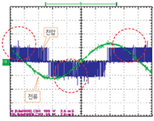
 PWM waveform including Transient
-
Before LCF installation
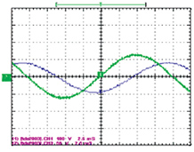
-
After LCF installation
Product Specification
게시판 리스트
| Type name |
Load capacity |
Enclosure dimension [mm] |
| HP |
kW |
HP |
D
|
H |
| LCF38001 |
1 |
0.75 |
350 |
500 |
500 |
| LCF38005 |
5 |
3.7 |
350 |
500 |
500 |
| LCF38008 |
7.5 |
5.6 |
350 |
500 |
500 |
| LCF38010 |
10 |
7.5 |
420 |
730 |
1000 |
| LCF38015 |
15 |
11 |
420 |
730 |
1000 |
| LCF38020 |
20 |
15 |
420 |
730 |
1000 |
| LCF38025 |
25 |
19 |
600 |
900 |
1200 |
| LCF38030 |
30 |
22 |
600 |
900 |
1200 |
| LCF38040 |
40 |
30 |
600 |
900 |
1200 |
| LCF38050 |
50 |
37 |
600 |
900 |
1200 |
| LCF38060 |
60 |
45 |
600 |
900 |
1200 |
| LCF38100 |
100 |
75 |
600 |
900 |
1200 |
| LCF38150 |
150 |
112 |
900 |
900 |
2150 |
| LCF38200 |
200 |
149 |
900 |
900 |
2150 |
| LCF38400 |
400 |
198 |
900 |
900 |
2150 |
※ A type name is based on voltage and HP (e.g., 440V, 1HP = LCF44001).
※ Parts can also be supplied. Therefore, it is possible to install them in existing or new panel.
※ Rated voltage 220V and 440V products are provided. A product size can be different depending on an installation location or condition. Therefore, please make sure to check it before placing an order.